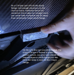
This is still going, I will try to take some pictures of my CT4 explain. I don't lift either the front or rear on the pinch flange, CT4 or CT5.
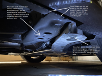
Front: If you take a close look at the pinch flange, you will notice that there is a reinforcement part right in the jack opening between the two panels, so the flange actually has 3 layers of metal there. That middle part is a big vertical bracket, sandwiched, that goes vertically up to body for reinforcement as a lift point (you can't see it, internal to rocker). Additionally, you will notice the plastic from the rocker on the outer side of the flange which makes me not lift there with the aftermarket aids (Zl1 add ons etc.). From a plant build standpoint, if you look on the inside of the car behind the aluminum shear panel, there is two round holes about 1-2" in diameter, those are body features used to hold the entire car fully assembled up in the air through the factory, so the pinch flange is not used while the manufacturing is conducted of our cars (body comes in bare on those, cars comes off with tires doors and everything from those onto a platform for first touch on tires at end of line).
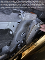
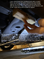
So, I lift just inboard of the pinch flange where that 3 layer metal is, I place a block of hardwood/aluminum, jam it against the front shear panel, now that block is locked by the pinch flange, by the shear panel bolt area and the inboard two hole feature, it can NOT slide or move and when you lift you are still engaging the vertical 3rd layer of the pinch flange, some of the plant body feature. Not far away from that, more forward, is another vertical bracket inside the rocker as well that provides a lot of structure, you just don't see it.
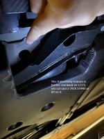
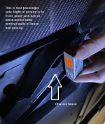
Rear: Similar body features for the manufacturing plant exist on rear, just closer to the pinch flange inboard wise. From a lifting standpoint the 4 and 5 differ on the rear. On the 4 the structural cradle brace to body blocks the pinch flange area, so you lift the 4 by placing jack or whatever across the two vertical walls of the brace just under the bolt or next to the pinch flange area, not far off. On the CT5 the rear brace is a bit different so you have room to lift on the pinch flange but you can lift just like the 4 on the brace, placing the jack stand on a big flat body feature just inboard of the pinch flange. You can also jack here if you have a block or room with your jack.
Long story shorty short, the pinch flanges are reinforced and work great if you have an aftermarket block or jack that pushes against IT (I don't enjoy bending them with jacks that have wheels, which is why I DO NOT lift there) but with our rockers, carbon fiber and other features make other areas easier for me. The rear is super simple and clear, use the chassis brace, done.
Hope this helps and all the best with the cars, I enjoy driving my 4 more and more and am already itching for another track day next year!

 I have only used the pinch welds for lifting the car in my garage because I know that other area is soft. I'll discuss that with them next time I have to take it in. This is what causes low dealer confidence.


